|

|
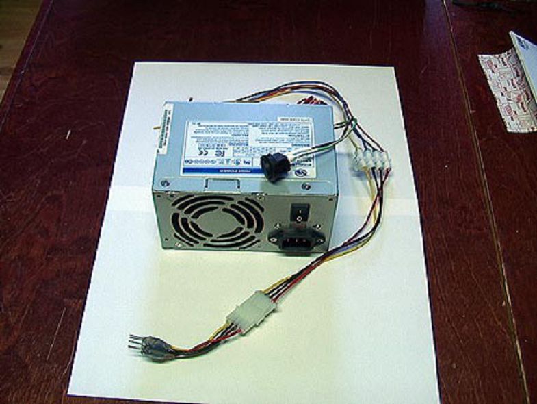
Here it is, looks snazzy don't it?!
|
Step 01: I used the pins of an old DIN audio connector from the 80's. Here it is above, totally broken showing 1 pin already extracted out of there. You will need 4 of these pins.
|

|

|
Step 02: Make sure they does fit into your Amiga power input by doing a test as shown above. Notice, that only 4 pins are needed as the one NOT connected is just shield. No need for that, we got ground pin already!
|
Step 03: Find yourselves a 4 pin power connector as shown above. The length of the wires you decide, I just happen to have a very short one for this project. Also, showing the 4 pins from the DIN connector extracted already.
|

|

|
Step 04: Get some tin solder on the end of the wires as shown in the bottom of the above picture.
|
Step 05: Now solder the DIN pins to the wires as shown here on the picture above.
|

|

|
Step 06: Then put some protection onto them, typically with a heater and heat-shrinkable tubing.
|
Step 07: Make sure they does fit into your Amiga power input again, by doing a test as shown above.
|

|

|
Step 08: Cut the wires from the ATX connector as shown above. Blue, Black, Green, Black, Red and Yellow. The wires cut here will be used in this project further down.
|
Step 09: Now, prepare the 1 x black and 1 x green cables which was cut loose from the ATX connector. You can barely see on the white connector which wires I'm referring to. These are used for a power switch.
|

|

|
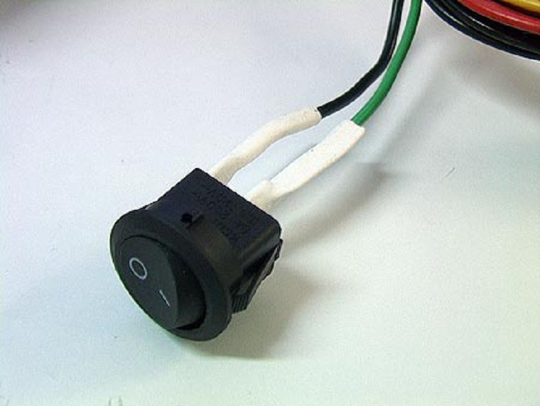
Step 10: Now, solder them on a 0 - 1 power switch as shown above
|
Step 11: Put some heat-shrinkable tubing on them too for security.
|

|

|
Step 12: Now, take the rest of the cut wires you got (yellow, blue, black and red) from the ATX connector and connect them to your 4 pin power connecter as shown above. If you are unsure of details, look on the next picture below, I had to use a additonal extension connector since my original cables where to short. You might just skip that and solder them directly. The important part is that you connect them as shown on the picture below anyway.
|
Step 13: Closeup of the extension connector. The wires in the lower part of the picture is from the cut wires from the ATX connector while the upper ones is to the 4 pin power connector.
|

|

|
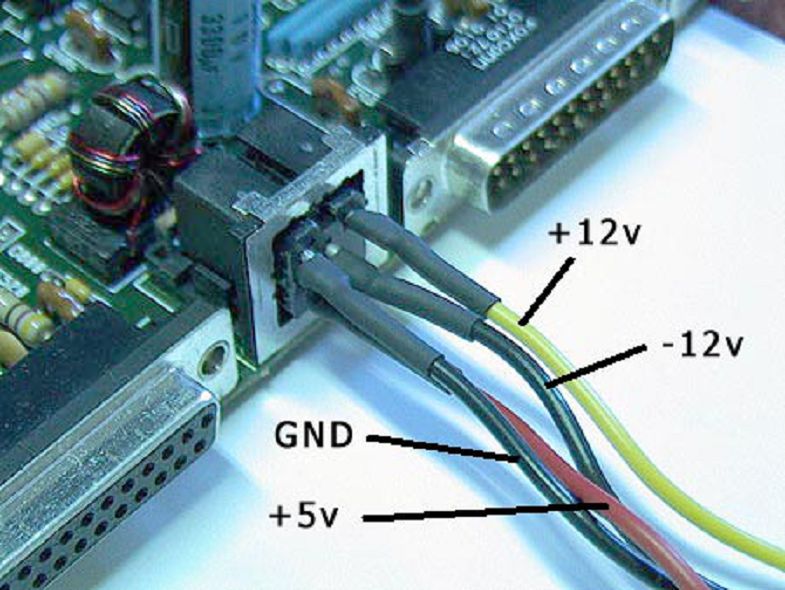
Step 14: Now put those DIN pins into the right positions of the Amiga power connector and prepare to glue them all together to form a custom made single power connector.
|
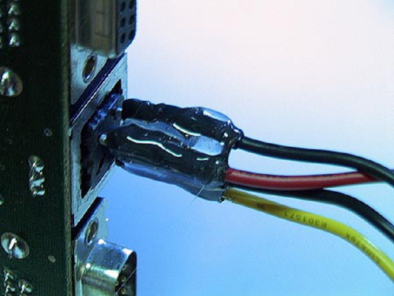
Step 15: While they are in place, put some hot glue onto them, starting from top. Wait until it had dried, then proceed to next step. Note that you must dismount the Amiga motherboard from its casing first, to get better accessability while gluing and turning over the motherboard. Make sure the hot glue also sneak in between the cables too!
|

|

|
Step 16: Turn the entire thing 180 degrees around and glue it there also. Now proceed to next step.
|
Step 17: Now, continue to glue it all around, all over the place.
|

|

|
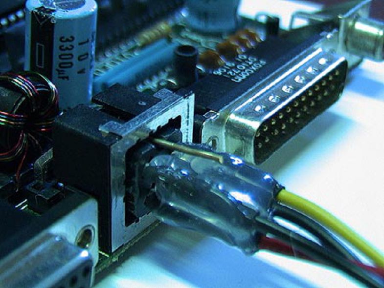
Step 18: Now, for the guiding pin. I used a metallic piece from a paper clip. Put it into the Amiga power connector as shown above and put it over the already glued connector.
|
Step 19: This is how it should look. If so, just go ahead and put some glue on it, as you can see on the right on the picture above.
|

|

|
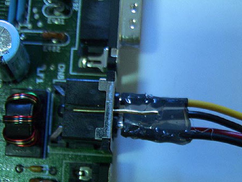
Step 20: Now, its fully glued onto the connector. Should be good enough. Wait for all glue to be cold before you extract it out of the Amiga connector!
|
Step 21: If done correctly, this is now how it looks after the glue has cooled. Nice.
|

|

|
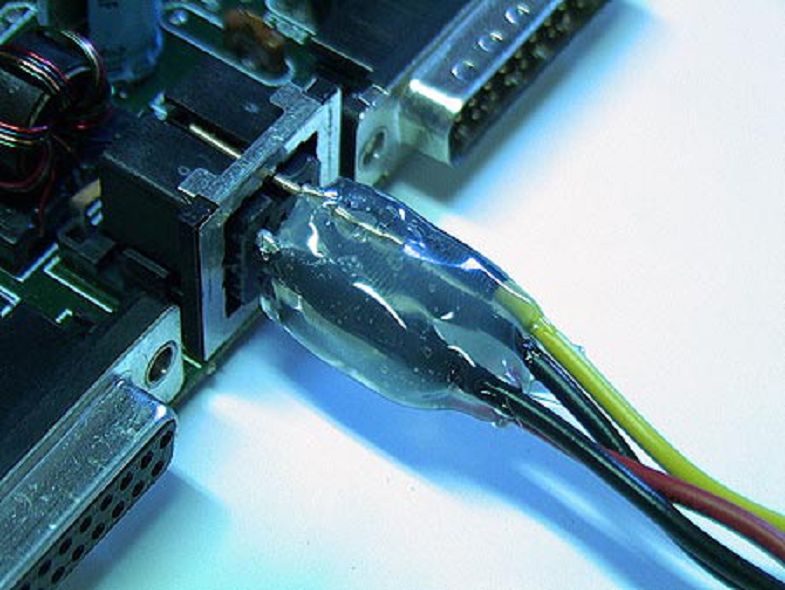
Step 22: Yes, look good from that view too! Just make sure you get glue around the inner area too, not just on the outside.
|
Step 23: It's all ready. Plug it back into your Amiga, and the other end into the 4-pin connector going to the ATX connector and power supply. And off you go!
|

|

|
Step 24: All connected, turn it on and.....does it work?
|
Step 25: It's working 100% allright. Yeah!
|

|
Summary: This is basically what you need to focus on. 4 wires and a power switch. Simple. Note that the ATX connector is seen from above, meaning the cables would be coming straight at you. See "Step 8? picture to see what I mean by that, if unsure.
|